This page documents my attempts to build an ARM-based server using a Gigabyte MP30-AR1 motherboard, running Debian.
This page was mostly written in September - November 2016, with minor updates since then; it was last updated 16th January 2020.
The Gigabyte MP30-AR1 is based on the Applied Micro X-Gene 1 processor; this has 8 64-bit ARM cores running at 2.4 GHz.
Mobile 64-bit ARM chips are reasonably widespread now; Apple have been using them in iPhones and iPads since 2013. Server or even desktop chips are rarer, and a breakthrough to widespread adoption seems permanently just around the corner:
Applied Micro seemed to be the best bet, as their X-Gene processor was actually shipping in a reasonably mainstream product, so I bought this Gigabyte board. But then, a few months later and before I'd got it fully functional, Applied Micro announced that they had been acquired by another company and intended to dispose of their ARM processor division "within 100 days". After rather more than 100 days they were bought by private equity firm Carlyle Group and are now called "Ampere" (website).
Apart from the processor the board is much more like a conventional PC motherboard than a typical ARM board; it has:
The price is also somewhat different from most "hobbyist" ARM boards; the motherboard (including processor) cost £449, and the total price once you have RAM, storage, etc. will be more like £700.
The presence of two PCIe slots opens up various opportunities not often found on ARM boards, such as fitting your choice of graphics card (one with open-source drivers, for example!) or using a fast M.2 SSD. I've not tried either yet.
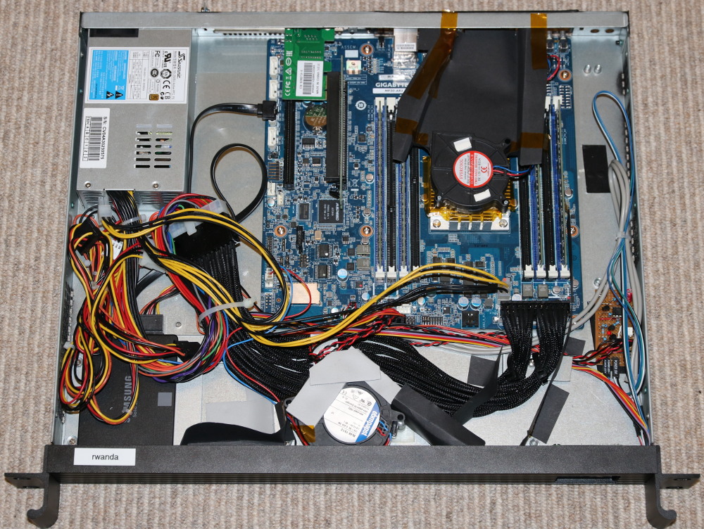
I put mine in a 1U rack-mount case along with a 2.5" SSD:
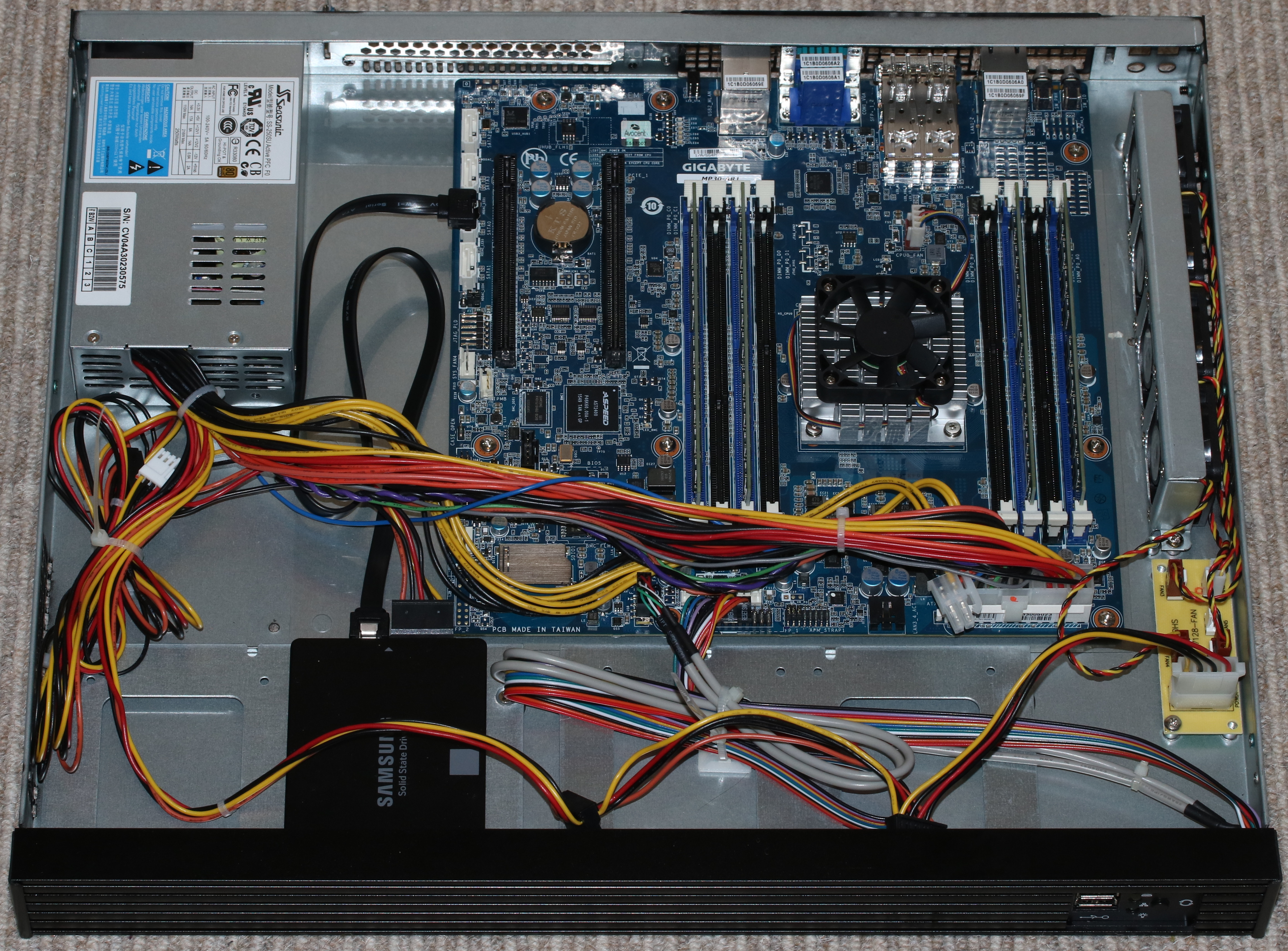
My Gigabyte MP30-AR1 in a 1U case; click to enlarge.
I bought most of the bits from X-Case.co.uk.
The board comes with no paper documentation. Various things are available from the Gigabyte website; these are spread over pages for three different products:
It's worth looking carefully through all of these as much useful information is hidden away. For example, the following block diagram is in the "MP30-AR0 Motherboard for APM X-Gene X3-408 processor User's Manual", which is on the R120-P30 page:
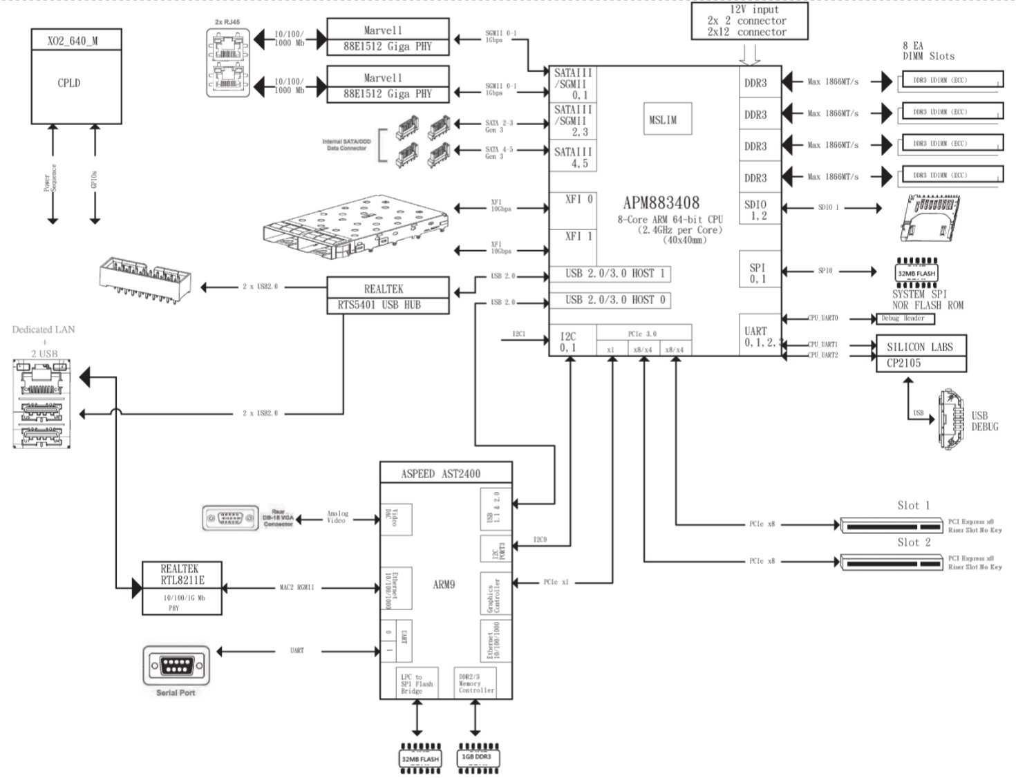
MP30-AR0 Block Diagram; click to enlarge.
Applied Micro's documentation is here; there is not much of interest apart from this block diagram of the processor:
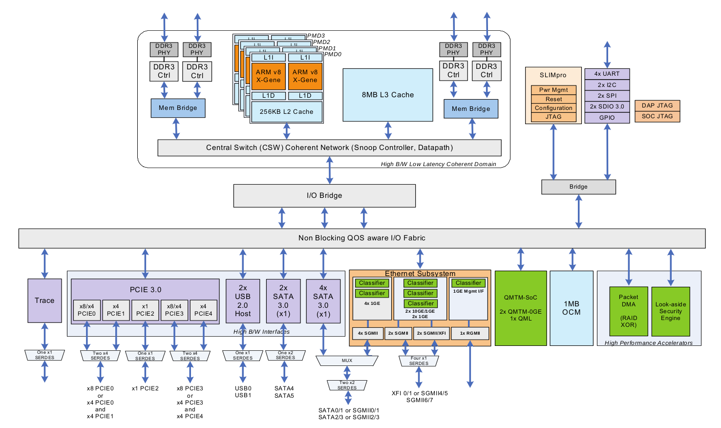
X-Gene 1 Block Diagram; click to enlarge.
In fact this is the worst-documented processor I've ever had to use. The contrast with the copious datasheets and manuals for the IXP4xx chips used in the NSLU2, about 12 years ago, is striking. Even by today's much lower standards the lack of public documentation is surprising.
When you're using an unconventional product it's very useful to know where to find support and a community of other users. For most ARM boards it's obvious where to go - you find the mailing list or web forum set up by the board's manufacturer (e.g. the ODROID-C2) or the group who have "repurposed" it (e.g. the NSLU2). In this case, however, it's not so clear - Gigabyte is a mainstream x86 motherboard manufacturer, and they don't seem to have set up anything specific for this board. Neither have Applied Micro, as far as I can tell. I have a feeling that there will be orders of magnitude fewer users of this board than of "hobbyist" ARM boards, and what support does exist from the manufacturers will be targeted at the sort of commercial customers who might one day order a million for their data-centre. This is unfortunate.
The main place that I've taken my questions is the Debian ARM mailing list; the people there have been helpful and some of them even have experience with this board or its predecessor. None of them know it inside-out though, and there are no participants from Gigabyte or Applied Micro. The main ARM Linux mailing list might have some more experts, but I've not found much during a quick look. The only other online resources that I've found are some posts by Richard WM Jones, who seems to have been working on getting RedHat to run on it. Unfortunately I think he may have an NDA with Applied Micro.
For kernel issues, I have had some success by directly emailing the people who wrote the relevent drivers at Applied Micro, perhaps CC'ing the relevent kernel list.
When mains power is applied, the board stays off. You have to press the power button to make it start. This is definitely not what you want on a server board, which is what this claims to be; you want it to be able to survive a power interruption with minimal downtime, not requiring a human to go to the machine and physically press a button.
Other PC motherboards have a setting in their BIOS to control this; you can choose "off", "on" or "previous state" for the behaviour after power loss. This board doesn't have any such setting, and I guess that it doesn't have the hardware to implement it. (The block diagram shows a CPLD that controls "power sequence"; that could do it, if it had some non-volatile storage.) Except that it does have a separate Baseboard Management Controller, which certainly could do this (though you'd have to wait for it to boot); if the software were open-source I could hack it, but it isn't.
This is really a pretty serious mis-feature for something that claims to be a server board. I've resorted to building a timer circuit that activates the power button shortly after mains power is applied:
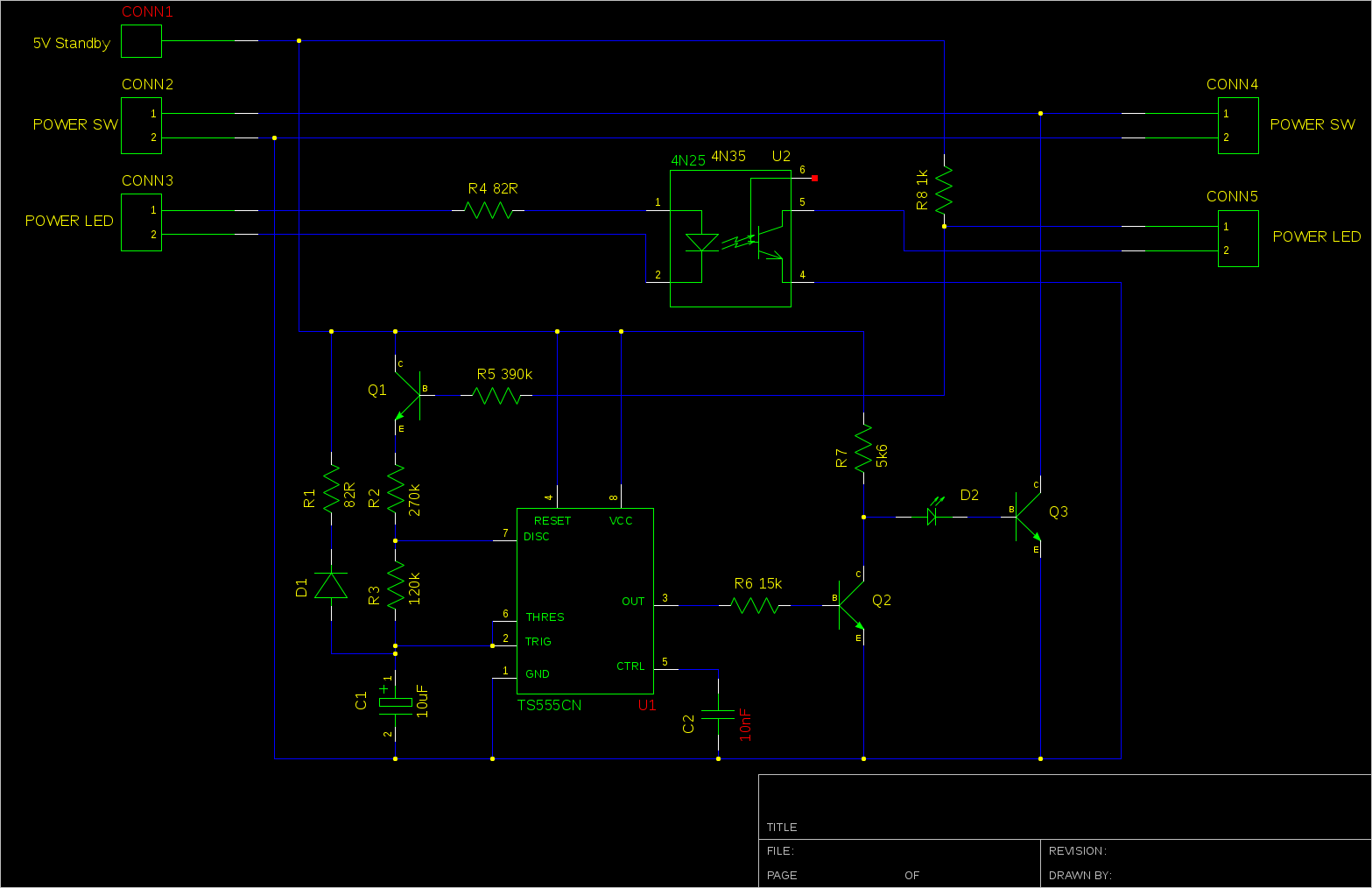
Power-On Circuit; click to enlarge.
The connections on the left go to the motherboard's front-panel connectors and those on the right go to the actual front panel. The 555 timer outputs a 1 second pulse about 6 seconds after power is applied, which "presses" the power button by turning on Q3. When the power LED comes on, the timer is prevented from repeating by turning off Q1. The opto-isolator is needed because the power LED output from the motherboard doesn't seem to be referenced to the same power supply. If for some reason the LED doesn't come on, the circuit will continue to "press" the power button every 4 seconds. D1 and R1 ensure that the timing capacitor is discharged properly even when the power is removed only briefly; LED D2 ensures that Q3 does not turn on spuriously while the supply voltage is below the 555's minimum. Note that the circuit requires that the front-panel LED is actually connected in order to work.
I've assembled this on a small piece of veroboard, which can be seen in the photos below.
You could probably get away with something much simpler, maybe just a capacitor across the power button, but I really want to be sure that this system doesn't get stuck off, and I like over-engineering things!
The arrangement shown in the photo at the top is noisy and runs quite hot. The CPU fan does fit in the space available in a 1U case - but only just, leaving not much space above to draw air in. It certainly doesn't get enough air circulation if you try replacing the supplied fan with a "quiet" one, as "quiet" fans seem to work by simply being slower than regular ones. This arrangement also seems to blow the hot air from the CPU directly at the RAM.
The case fans are also not ideally located at the back right. The normal arrangement in a rack case is to draw air in at the front and out at the back.
My first attempt at reorganising it was to move the supplied bank of case fans to the front. This worked OK, but first one then a second of the four fans got noisy. I decided to replace them, but while I was researching reliable 40mm fans I decided that a centrifugal blower fan would be a better choice; centrifugal fans are better when the static pressure is high, as is typical with a 1U case.
I am using a 76mm x 27mm EBM Papst RL48-19/12; this has only two wires so speed monitoring is not possible. This doesn't matter though - fan speed monitoring doesn't work on the motherboard's system fan connections; they are reported as 'N/A'.
I've then constructed card baffles to duct the air towards the CPU. Unfortunately quite a few cables get in the way, but I've used a power extension anchored to the bottom of the case to increase the space. This would have worked better if the case had the power supply on the other side.
I would have liked to use an off-the-shelf CPU cooler designed for a 1U case, but unfortunately they are all designed for standard Intel or AMD mounting hole positions. This CPU is significantly smaller, so instead I've improvised by fitting a blower fan on top of the supplied heatsink. It's a 15mm thick, 60mm diameter "Evercool" fan. This has reversed the airflow through the heatsink fins, which has the benefit of not directing the hot air at the RAM. I've then ducted the output of the blower to a space on the back panel above the unused SFP+ slots.
Unfortunately I was unable to find a suitable fan with 4-wire control. (Please let me know if you know where to get one!) Even a 3-wire fan was difficult to get in the right size. As a result the fan now runs at full speed - so it's just as noisy as the original.
Modified layout with replacement fans.
With this arrangement, with an ambient air temperature of 16C, I see an idle CPU temperature of 42C. The reported RAM and motherboard temperatures are in the range of 25-32C. When busy, the CPU gets up to something like 75-80C and the other sensors rise by about 5C; that's with all CPU cores doing something, but it's not intended to be a "max power" test.
I think that's just about OK. The BMC (see below) is configured with a non-critical limit of 100C and a critial limit of 105C for the processor, 75/80 for the RAM and 55/60 for the motherboard. I'd feel happier if the CPU temperature was a bit lower, but it's not obvious how to achieve that.
It's interesting that Applied Micro's "Mudan" 1U server design doesn't seem to have a CPU fan at all.
This has been my first experience of UEFI, which is apparently used a lot as a boot environment on newer x86 systems. The idea is that the UEFI implementation starts at power-on and looks for bootable operating systems on each storage device. It then chooses one, possibly by presenting a menu on screen, and runs it. In the case of Linux, this is probably GRUB which adds another level of indirection before the actual kernel starts. Once the kernel has started it can continue to use UEFI services for things such as ACPI.
The previous MP30-AR0 shipped with U-Boot instead of UEFI, and some users chain-loaded a free UEFI implementation from U-Boot called TianoCore. This is not the same as has been supplied with the MP30-AR1; this implementation is by American Megatrends:
Boot from SPI-NOR
American Megatrends
Boot firmware (Project MP30-AR1, BIOS Ver F01; built at 15:11:23 on Sep  5 2016)
Slimpro FW Ver: 2.4
iPP Ver: 01.20.05.00
Its most obvious feature is that it is extraordinarily slow. It takes 3 minutes to show a Gigabyte logo on the screen. It gives the impression that it is emulating x86 code, or running from a serial ROM, or something.
Another difference from the MP30-AR0 is that that board apparently included a small Linux distribution on the same flash device as U-Boot, so it was possible to boot into Linux without any storage attached. The newer board still has a boot menu entry for this, but the actual Linux system doesn't seem to be present; perhaps UEFI is too large to leave any space for it.
UEFI sends lots of debugging to the serial port (at 115200 baud), and it's worth connecting a terminal so that you know something is happening during the long wait for it to boot.
At the time when I got the board the standard Debian installer didn't work with it due to various kernel issues, and it took me a while to get it working. I then built my own Debian kernel package.
I believe that those issues have now been fixed, and the stock Debian kernel does work on the board. I think this should mean that the stock Debian installer will also work, but I've not actually tried that.
The installation process shoud be something like:
console=ttyS0,115200 console=tty0 earlycon=uart8250,mmio32,0x1c020000
As I initially had some trouble installing Debian I tried a couple of other distributions, which seemed to work better. The Centos ARM64 installer works and installs a working system, as does the Ubuntu installer. It is probably necessary to edit the kernel command line from GRUB for both of these to set up the serial console.
This was the issue that I spent most time trying to resolve, but it does now seem to work. I needed to get I2C working so that I can use IPMI to talk to the BMC to get temperature sensor readings (see below).
My understanding is that the I2C master is part of the "SLIMpro" co-processor, and the driver in linux/drivers/i2c/buses/i2c-xgene-slimpro.c makes it accessible from the main processor via a "mailbox". Like a lot of kernel code this is not explained anywhere except in the commit message introducing the new file.
(The Applied Micro block diagram above shows the "SLIMpro" block but not "MSLIM"; the Gigabyte block diagram shows "MSLIM" but not "SLIMpro". Both are described in the Applied Micro "product brief". "MSLIM" is described as a cluster of four ARM A5 processors at 500 MHz which "can be used to provide acceleration to the system". "SLIMpro", meaning "Scalable Lightweight Intelligent Management processor", is described as a dedicated 32-bit processor that provides "dynamic power management and higher layer network acceleration".)
After much debugging I came to the conclusion that the i2c-xgene-slimpro.c driver has no chance of working on a system that's using ACPI - although that file seems to have ACPI support, the mailbox code that it talks to needs a device tree. So I asked myself why I was using ACPI; it's simply because the first kernel that I got to boot was a CentOS one that uses ACPI, and because Hector Oron mentioned a bug in the device tree provided by the firmware. I don't know exactly what that bug is, but one issue he mentioned is with more than 32 GB of RAM; I have 32 GB, so that's not an issue for me. Anyway, when I tried my 4.7.2 kernel without acpi=force, so that it booted using device tree, it worked! (By which I mean, it booted. The I2C didn't spring into life, but it got beyond the error that occurred in ACPI mode.)
I then discovered - eventually - that /dev entries for i2c don't appear unless you load the i2c-dev module. Having done that I got /dev/i2c-0, and some IPMI functionality started to work - but most IPMI activity would soon cause a kernel oops. After a great deal more debugging - literally weeks of work - I tracked this down to a buffer overrun in i2c-xgene-slimpro.c; it declares a DMA buffer in struct slimpro_i2c_dev of size I2C_SMBUS_BLOCK_MAX, but it needs to be at least one or two bytes longer than that. (See this commit; it ended up in 4.9 or 4.10 and stable updates of 4.4 and 4.8.). With that fixed I now seem to have reliable I2C.
The MP30-AR1 has a "baseboard management controller", or BMC; this is a separate processor with its own flash, RAM and network interface - running Linux, of course. Its separate network interface provides a web interface from which it's possible to power the main processor on and off (the BMC is powered whenever the mains is connected), observe fan speeds and temperatures, upgrade the main processor's boot software and various other functions. A user guide is available, but it all seems reasonably straightforward.
Note that that BMC's network interface seems to be 10/100 Mbit only, contrary to some documentation that claims it to be gigabit. One consequence of this is that you cannot loop it back to one of the main network connections, as they seem incapable of operating at below gigabit speed (see below).
The web interface claims to be able to report power consumption, but unfortunately this doesn't seem to work; it would have been useful if it did.
As well as the web interface, the BMC is accessible using IPMI over the network; you can use ipmi-sensors from FreeIPMI to read the sensors:
$ /usr/sbin/ipmi-sensors -h rwanda_bmc -u admin -p password
ID  | Name       | Type                   | Reading    | Units | Event
4   | CPU0_TEMP  | Temperature            | 80.00      | C     | 'OK'
9   | DIMM_P0_A0 | Temperature            | 31.00      | C     | 'OK'
10  | DIMM_P0_A1 | Temperature            | N/A        | C     | N/A
12  | DIMM_P0_B0 | Temperature            | 32.00      | C     | 'OK'
13  | DIMM_P0_B1 | Temperature            | N/A        | C     | N/A
15  | DIMM_P0_C0 | Temperature            | 29.00      | C     | 'OK'
16  | DIMM_P0_C1 | Temperature            | N/A        | C     | N/A
18  | DIMM_P0_D0 | Temperature            | 30.00      | C     | 'OK'
19  | DIMM_P0_D1 | Temperature            | N/A        | C     | N/A
59  | P12V       | Voltage                | 11.89      | V     | 'OK'
60  | P5V        | Voltage                | 5.04       | V     | 'OK'
61  | P3V3       | Voltage                | 3.27       | V     | 'OK'
62  | P5V_STBY   | Voltage                | 5.06       | V     | 'OK'
64  | P_VBAT     | Voltage                | 3.10       | V     | 'OK'
65  | P_VCCP     | Voltage                | 0.99       | V     | 'OK'
66  | P_1V2_HUB  | Voltage                | 1.20       | V     | 'OK'
67  | P_VDDQ_AB  | Voltage                | 1.50       | V     | 'OK'
68  | P_VDDQ_CD  | Voltage                | 1.50       | V     | 'OK'
71  | P_0V9_VDD  | Voltage                | 0.96       | V     | 'OK'
72  | P_1V5_VDD  | Voltage                | 1.50       | V     | 'OK'
73  | P_2V5_VDD  | Voltage                | 2.53       | V     | 'OK'
74  | P_1V8_VDD  | Voltage                | 1.80       | V     | 'OK'
136 | CPU0_FAN   | Fan                    | 5700.00    | RPM   | 'OK'
138 | SYS_FAN1   | Fan                    | N/A        | RPM   | N/A
139 | SYS_FAN2   | Fan                    | N/A        | RPM   | N/A
140 | SYS_FAN3   | Fan                    | N/A        | RPM   | N/A
141 | SYS_FAN4   | Fan                    | N/A        | RPM   | N/A
186 | PSU1       | Power Supply           | N/A        | N/A   | N/A
190 | CPU0       | Processor              | N/A        | N/A   | 'Processor Presence detected'
202 | MB_TEMP1   | Temperature            | 32.00      | C     | 'OK'
203 | MB_TEMP2   | Temperature            | 31.00      | C     | 'OK'
204 | MB_TEMP3   | Temperature            | 25.00      | C     | 'OK'
205 | SEL        | Event Logging Disabled | N/A        | N/A   | 'OK'
It may or may not be necessary to add "-D LAN_2_0" to the command line to make that work.
(I'd love to know where the three motherboard temperature sensors are.)
It is also possible to do the same thing using IPMI over the SMBus and get the sensor data from the main processor without going over the network. (SMBus is an I2C variant; SSIF is "SMBus System Interface".)
ipmi-sensors will by default now use this connection to the BMC.
(An alternative is to have the user-space IPMI tools talk directly to I2C, rather than doing that in the kernel. To do this, don't load the two ipmi kernel modules but instead load i2c_dev. You'll get /dev/i2c-0. Then configure FreeIMPI with driver-type SSIF, driver-device /dev/i2c-0 and driver-address 0x10. This has the disadvantage that other packages may only understand the /dev/ipmi* interface, for example collectd's IPMI plugin.)
Unfortunately the reported temperatures are not entirely reliable; periodically, a spurious too-high or too-low value is seen:
4   | CPU0_TEMP  | Temperature | 46.00      | C     | 'OK'
4   | CPU0_TEMP  | Temperature | 46.00      | C     | 'OK'
4   | CPU0_TEMP  | Temperature | 30.00      | C     | 'OK'
4   | CPU0_TEMP  | Temperature | 46.00      | C     | 'OK'
4   | CPU0_TEMP  | Temperature | 46.00      | C     | 'OK'
Those readings are five seconds apart.
This doesn't seem to affect the voltage readings, but can be observed on both IPMI-over-I2C and IPMI-over-LAN. I've not tried looking in the values shown in the web interface. Maybe it's a bug in the BMC, or maybe a hardware bug related to the BMC's connection to the sensors.
This makes it more difficult to set up monitoring and alarms.
The BMC also provides "KVM over IP", i.e. you can interact with the system's keyboard, video output and mouse remotely via the BMC's network connection. It achieves this by connecting to the main processor by PCI and implementing a graphics controller. This is a basic graphics controller without e.g. 3D acceleration and it also drives the system's VGA output. Keyboard and mouse are implemented by means of a USB connection to the main processor, which is also used to implement remote virtual media, i.e. a fake USB flash drive. The implementation is by Avocent.
Unfortunately the client is a Java viewer app which is invoked from the BMC's web interface. This doesn't seem to work on my Linux desktop; on my Mac I hesitantly installed a Java runtime and it did seem to display an image of the console. It would be great if it simply used VNC; simply being able to see a screenshot in the web interface would also be useful.
It's also possible to redirect the serial port to the network, which could be just as useful as the KVM function. The mechanism for this is part of IPMI and a client is included in FreeIPMI.
Apparently the BMC supports a shared network mode where it uses a side-channel to talk to one of the main CPU's network ports, rather than using its own dedicated network port. According to the (non-board-specific) documentation for the BMC you can enable this in the web interface by changing the "mode" setting in the general network settings screen BUT DO NOT DO THIS:
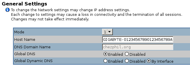
It seems to me that this shared mode doesn't work on this board, and once changed it's hard to reset it. I was eventually able to restore it to its default but first I explored a lot of dead ends.
The BMC has a serial console which is accessible via a pin header; this is described in the MP30-AR0 software reference guide. The connector is near the mounting screw hole on the bottom left of the board, as viewed in the photo above; it's miss-labelled "JTAG_BMC". The pin nearest the screw hole is VCC (about 1.6V), the pin furthest away is ground, and the others are transmit and receive data (only two combinations to try). Connect with an RS232 level shifter (mine is designed for 1.8V but works fine); it runs at 115200 baud.
It outputs lots of stuff when the board boots and then presents a login prompt. I've not yet found a username and password that works, see below.
The BMC also seems to have an ssh daemon running, but this is for an IPMI service, not a shell; its credentials are the same as the web interface. The web interface credentials don't work on the serial console.
A BMC firmware update ZIP file is available. This contains the firmware files as well as some utilities for programming it. These include 64-bit ARM Linux executables.
At first I assumed that the Linux utilities would not work because of my lack of an IPMI I2C device, so I tried various other things. I discovered that they also ship a set of ARM UEFI executables. These might have worked, except that they were undocumented and the one that I guessed was the firmware update program (Bmcfwu.efi) just hung whenever I tried to run it. (It seems that ctrl-c doesn't work in the UEFI shell; in fact I think that the ctrl key doesn't work at all in UEFI and GRUB.)
I also looked at the content of the firmware; the flash.sh script has enough clues to work out how to extract the root filesystem image using dd. It's a squashfs3 image, which is too old for modern kernels to loop-mount, but unsquashfs from squashfs-tools will unpack it. I didn't look in detail at the contents but I did find /etc/default/passwd and /etc/default/shadow. (The actual passwd and shadow files are symlinks to outside the squashfs, so I can't be sure that this is what's actually used.)
The unshadow of it is:
avct:$1$qg6UcA2k$STBswpilcP6l8tQculG/k0:0:0:avct:/:/bin/sh
sshd:*:74:74:Privilege-separated SSH:/var/empty/sshd:/sbin/nologin
I have been told that the avct password hash is for avctr00t - I've not tried this to see if it works.
(Running "John the Ripper" could be an interesting benchmark; it manages about 4470 guesses per second per CPU, if I've understood the statistics correctly. The CPU temperature reaches 80C, with the lid off. That can be compared with the performance of other systems described here.)
When I did eventually investigate the Linux utilities I discovered (using strace) that they try to communicate with the BMC over PCI, which seemed more likely to work than I2C. They weren't working because /sys/bus/pci/devices is empty when I boot with ACPI enabled. Booting with ACPI off, the PCI devices appeared in the expected places and the utilities were able to reflash the BMC! It seems that the difference between the supplied flash.sh and flashall.sh scripts is that the latter resets the user settings, and that was what I needed to restore my network connection! Success!
The board accepts DIMMs with error correction. In order to get statistics about the number of errors found you need a kernel with CONFIG_XGENE_EDAC enabled. Then install edac-utils.
The two gigabit ethernet ports don't work if connected to a 10/100 Mbit/s switch; they fail to auto-negotiate down to the lower speed. This is important to me as this box may end up connected to a 100 Mbit/s switch. It also means that it's not possible to loop the BMC management port to one of the main network ports.
Interestingly, watching my switch's web interface it seems that they do come up at 100 Mbit/s while UEFI is booting. They then go down, and fail to come back up when Linux tries to initialise them. I spent a long time trying to understand this. The driver tells the PHY to start auto-negotiation but it fails to come up.
I eventually contacted the author of the X-Gene network driver at APM, and he believes the problem is that the addresses of the two PHYs on the MDIO bus are 0 and 1. 0 is apparently a "special" address in some sense which should not have been used. He believes that this should be fixable either in the Linux driver or in the firmware.
That might be fixed eventually, but I've given up waiting and installed a PCIe ethernet card with a Realtek chip on it. This autonegotiates without any problems.
It did take quite a while to get this card it to use the interface name that I wanted, though; I wanted to call it eth4, but it came up as enp1s0. Apparently this is a new default for persistent interface naming. Fine, but instructions for changing it using a .link file in /etc/systemd/network don't work; it seems that you need to use udev rules on Debian stretch.
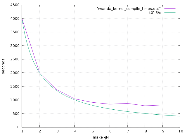
Here is a graph of kernel compilation times versus make concurrency. The green line shows the ideal execution time if perfect speedup were achieved.
Here is the same data expressed as speedup:
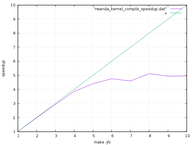
It's pretty clear from this that speedup is almost perfect up to 4 CPUs; it has fewer serial bottlenecks than my quad-core Cortex-A53 ODROID-C2. Beyond this however it deteriorates quite quickly for this workload - the final 4 CPUs contribute additional speedup of only 1.27. I believe that the CPUs are paired, sharing L2 caches, which may explain this.
These graphs are directly comparable with those for the ODROID-C2 - it's the same kernel being compiled - so we can see that when both are using a single CPU the MP30-AR1 is 1.85 times faster than the ODROID-C2. Its clock speed is 1.6 times faster (2.4 GHz vs. 1.5 GHz) so this seems reasonable, though you might have expected a greater difference as the processor is supposed to be architecturally more advanced i.e. out-of-order execution. When both use 4 CPUs it is 2.4 times faster, and when both use all of their CPUs it is 3.2 times faster. Performance per watt and performance per $ will both be much worse though!
pbzip2 is a parallel implementation of the bzip2 file compression algorithm. It works by separately compressing portions of the input file, so that the sections can be decompressed in parallel; a file compressed by pbzip2 can be decompressed by regular bzip2, but a file compressed by regular bzip2 can be decompressed by pbzip2 only without any speedup.
This test pipes the output of the pbzip2 decompressor into tar, so there is the serial overhead of tar and the filesystem to account for.
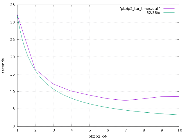
Again the speedup eventually tails off, but respectable speedups are being achieved for the first few CPUs.
Here are the results from some sysbench CPU test runs; they show good linear speedup up to 8 CPUs. The actual speed, however, is fractionally slower than my ODROID-C2!
$ sysbench --num-threads=1 --test=cpu --cpu-max-prime=20000 run
sysbench 0.4.12:  multi-threaded system evaluation benchmark

Running the test with following options:
Number of threads: 1

Doing CPU performance benchmark

Threads started!
Done.

Maximum prime number checked in CPU test: 20000


Test execution summary:
    total time:                          25.9322s
    total number of events:              10000
    total time taken by event execution: 25.9304
    per-request statistics:
         min:                                  2.59ms
         avg:                                  2.59ms
         max:                                  2.74ms
         approx.  95 percentile:               2.59ms

Threads fairness:
    events (avg/stddev):           10000.0000/0.00
    execution time (avg/stddev):   25.9304/0.00

$ sysbench --num-threads=2 --test=cpu --cpu-max-prime=20000 run
sysbench 0.4.12:  multi-threaded system evaluation benchmark

Running the test with following options:
Number of threads: 2

Doing CPU performance benchmark

Threads started!
Done.

Maximum prime number checked in CPU test: 20000


Test execution summary:
    total time:                          12.9670s
    total number of events:              10000
    total time taken by event execution: 25.9290
    per-request statistics:
         min:                                  2.59ms
         avg:                                  2.59ms
         max:                                  3.13ms
         approx.  95 percentile:               2.59ms

Threads fairness:
    events (avg/stddev):           5000.0000/1.00
    execution time (avg/stddev):   12.9645/0.00

$ sysbench --num-threads=4 --test=cpu --cpu-max-prime=20000 run
sysbench 0.4.12:  multi-threaded system evaluation benchmark

Running the test with following options:
Number of threads: 4

Doing CPU performance benchmark

Threads started!
Done.

Maximum prime number checked in CPU test: 20000


Test execution summary:
    total time:                          6.4835s
    total number of events:              10000
    total time taken by event execution: 25.9274
    per-request statistics:
         min:                                  2.59ms
         avg:                                  2.59ms
         max:                                  2.64ms
         approx.  95 percentile:               2.59ms

Threads fairness:
    events (avg/stddev):           2500.0000/0.00
    execution time (avg/stddev):   6.4818/0.00

$ sysbench --num-threads=8 --test=cpu --cpu-max-prime=20000 run
sysbench 0.4.12:  multi-threaded system evaluation benchmark

Running the test with following options:
Number of threads: 8

Doing CPU performance benchmark

Threads started!
Done.

Maximum prime number checked in CPU test: 20000


Test execution summary:
    total time:                          3.2494s
    total number of events:              10000
    total time taken by event execution: 25.9281
    per-request statistics:
         min:                                  2.59ms
         avg:                                  2.59ms
         max:                                  2.73ms
         approx.  95 percentile:               2.59ms

Threads fairness:
    events (avg/stddev):           1250.0000/2.55
    execution time (avg/stddev):   3.2410/0.01
mbw is a simple single-threaded memory bandwidth test.
$ mbw 8192
AVG	Method: MEMCPY	Elapsed: 1.93245	MiB: 8192.00000	Copy: 4239.187 MiB/s
AVG	Method: DUMB	Elapsed: 1.54521	MiB: 8192.00000	Copy: 5301.538 MiB/s
AVG	Method: MCBLOCK	Elapsed: 0.77593	MiB: 8192.00000	Copy: 10557.623 MiB/s
Running two instances of mbw concurrently seems to show a linear slowdown, i.e. a single CPU is able to use all of the approximately 10 GB/s main memory bandwidth.
There doesn't seem to be any support for either frequency scaling or CPU hotplug, so all 8 CPU cores are running at 2.4 GHz at all times. This surely results in considerable wasted power consumption when idle. My guess is that this is a hardware limitation, but it's possible that it might be fixable in software.
Power consumption, measured at the wall, is about 43W when idle. When busy using all processors - running tar and pbzip2 - it increases to about 71W.
I don't really know how that compares with current x86 systems. It is certainly a lot higher than any other ARM system I've used! I think that just the fans are using more power than my ODROID-C2.
It's unfortunate that kexec doesn't yet work as it would make reboots much quicker, bypassing the horrible UEFI. I believe it will be ready soon.
An oddity of the Debian GRUB, probably related to the UEFI implementation, is that its 5-second countdown before booting the default choice runs at about an eighth of the correct speed. But the Ubuntu GRUB doesn't seem to suffer from this problem.
I don't think I've received an offer of source code for the Linux and busybox in the BMC. Source is available for the small linux implementation that was supplied along with U-Boot in the MP30-AR0 board.
I do still see kernel stack traces during boot, though these don't actually seem to break anything. Other boards with American Megatrends ARM64 UEFI are reported to have the same issue. I also see other apparently-harmless errors, including:
[Firmware Bug]: IRQ flags corrupted (0x00000140=>0x00000100) by EFI set_time
[Firmware Bug]: IRQ flags corrupted (0x00000140=>0x00000100) by EFI get_time
This board's greatest strength is that it actually exists. There are plenty of "vapourware" alternatives - for example, at least three based on AMD's non-existent ARM64 server chip - but I just gave up waiting for them. The other nice features are the SATA and PCIe interfaces, the possibility of using lots of RAM, and the supposed "server class" build quality. ARM64 support in the kernel, Debian (and other distributions), compilers etc. is excellent (and well ahead of the hardware).
Against that, though, there are some significant disadvantages. It's expensive, and because it's based on a now relatively old process technology (40nm) it is power-hungry and not massively high performance. The future of Applied Micro's proessor division is currently unclear. You need to be an "ARM geek" to choose it.
It also has some very rough edges, such as the embarrassingly slow UEFI boot times, the lack of power on "on", the broken ethernet auto-negotiation, and the bugged I2C that I wasted so much time trying to make work. And there's the lack of "community" and documentation to consider.
It reflects badly on the ARM ecosystem that this is the best that we have.
I had been planning to put this machine in a co-location facility somewhere, but my numerous concerns made me nervous and instead I chose to use a virtual machine from Scaleway.
Like the APM board this had 8 ARM64 CPUs, but it had only 8 GB of RAM; they offer various configurations. The hardware is Cavium ThunderX. Comparing the two, in a very rough benchmark the APM processors seem to be 2.5 times faster than the Cavium ones - which is quite a substantial difference. I think the clock speeds are supposed to be comparable. But if I wanted twice the performance I could upgrade to 16 CPUs (for parallelisable tasks).
The most obvious difference, though, is price; Scaleway were charing me 11.99 Euro / month for this. It would have taken me at least 6 years before I would have even paid the cost of the APM hardware, let alone co-location charges.
I kept the Scaleway VM for a few months, but gave up on it due to various reliability issues that were probably not specific to the ARM hardware (I would not recommend Scaleway). At about the same time, AWS launched their ARM instances, which I have experminted with briefly but am not using extensively.
This isn't the ending that I was hoping for. Maybe things will be better in a few years? Or is it a case of "ARM Servers - technology of the future. Always has been, always will be."