Zigbee, formally IEEE 802.15.4, is another short-range radio standard that uses the 2.4 GHz "microwave oven" band, alongside wireless Ethernet and Bluetooth. Compared to these others, Zigbee is most suited for low-power applications involving simple microcontrollers, for example wireless sensing, home and industrial automation, and so on. Its basic parameters are a data rate of up to 250 kbits/s and a typical range of 50 m.
A small Linux box like the NSLU2 (aka Slug: 266 MHz XScale ARM processor, filesystem on a USB flash drive, takes about 5W, runs Debian GNU/Linux and other distributions) could be useful in a Zigbee deployment. For example, an always-on Slug could be responsible for logging data sent by remote sensors, and generating graphs on web pages, sending email alerts and so on. I decided to have a play.
Building a 2.4 GHz radio from the chips is a bit beyond my soldering ability, so I looked for modules and found five. They're all quite cheap.
I've used DLP's products before and they are readily available in the UK from FTDI in Glasgow. Since their modules also have the advantages of built-in USB at the host end and processor-less operation at the remote end, I bought a pair.
Here's the USB end, mounted in a little box and ready to connect up to the Slug:
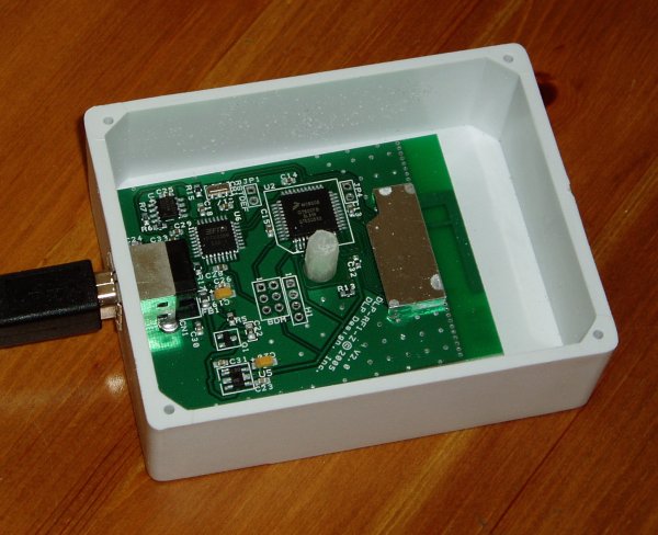
The RF chip is under the screening can on the right; it's tiny. The F-shaped PCB track to the right of the can is the aerial. Above the fixing post in the center is the microcontroller, and to the left of that the USB-to-Serial chip (an FT232) and an EEPROM for the USB configuration data.
The same microcontroller is used at both ends; it's a Freescale (aka Motorola) MC9S08GT60 and reading the microcontroller datasheet alongside the fairly brief DLP documentation is a good idea.
Here's the remote end. It needs a supply of between 2 and 3.4 V; I'm using 3.0 V. Because the 10x2 0.1-inch connector won't plug directly into my breadboard I built a small breakout board, also pictured:
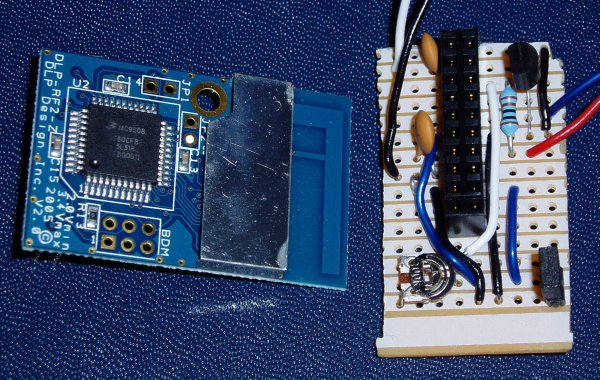
Unfortunately after a few hours of testing the remote end blew itself up, and now behaves like a 5 Ohm resistor across the power supply. I can only guess that either I gave it a static zap, or maybe my bench power supply fried it. I am being extra-careful with the replacement.
The breakout board performs various useful functions:
When plugged in to the Slug the host board appears as a USB serial device, using the FTDI kernel module. Unlike my other Slug FTDI projects where I've bypassed this module and accessed the chip using libftdi, in this case I am treating it as a serial port. The protocol uses a simple packet format with packet length, destination and source node IDs, a one-byte command and a variable-size payload. IDs are 16-bit, so you can have up to 65536 nodes in your network. Packet flow is as follows:
Packet transmission is unreliable, so application code needs to cope with failures and retry as appropriate.
I wrote some simple C++ code to send and receive these packets; you can get the source using Subversion or browse online at http://svn.chezphil.org/slugbee/trunk/. It's available under the terms of the GNU GPL. Here's an example using my "slugbee" utility:
$ ./slugbee
Usage: slugbee <port> <destination> <command> [args...]
  commands are:  ping
                 measureenergy
                 setupadc <channel> <state>
                 readadc  <channel>
                 setiopindir <pin> <1=out, 0=in>
                 readiopin <pin>
                 writeiopin <pin> <val>
                 readeeprom <addr>
                 writeeeprom <addr> <data>
$ ./slugbee /dev/ttyUSB0 2 readadc 1
Sending packet: source: 1  destination: 2  command: ae  data: 1
Got packet: source: 2  destination: 0  command: ca  data: 0 0
Having got this far I needed something real to apply it to, and decided to monitor the power output from my solar panel.
I have a small solar panel fixed to the wall of my house for experimental purposes, and have been curious to know how its practical power output compares to the nominal 4.8 Watts that its box claims. So I kludged together the awful mess pictured below:
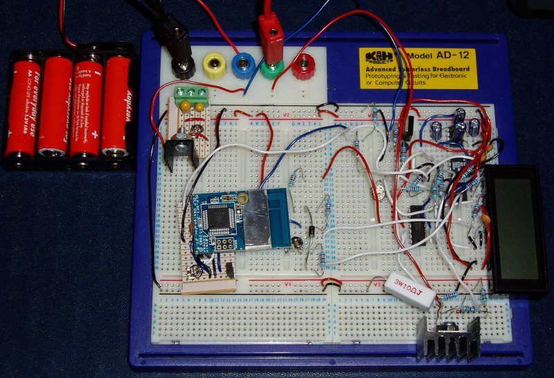
Here is what it does:
If I didn't want the panel meter I could have made it all a lot simpler by separately measuring the current and voltage and multiplying them in software. I actually have another reason for wanting to compute the analogue power: I want to upgrade to a maximum power point tracker, rather than the dumb load that I have at present, and that will need the power as one of its inputs.
One of the best features of the DLP module is that it can be programmed to go into a very low power sleep mode, taking less than 35 uA, and to wake up periodically. This mode is enabled by the jumper on the bottom right of the breakout board. The wake-up interval is programmable. On wake-up it sends a broadcast packet which my Slug logger software waits for.
On receipt of the broadcast packet, the logger sends commands to:
The results are sent to a PostgreSQL database on my webserver (a virtual machine). With the logged results in a database you can do all sorts of dynamic reporting and analysis: you can see some basic graphs on the Solar Log page. The graphs are generated with Ploticus. The source code for the logger can also be found at the address given above.
Do get in touch if you would like to know any more about this project, or if you think I can help with your low-power remote logging and control applications.