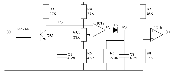
Circuit for the frequency monitor. Download postscript.
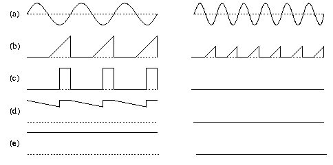
Typical waveforms for signals within the frequency monitor for low and high speeds. Note that these are idealised waveforms. Download postscript.
During the positive half-cycle of the dynamo output a, current flows through R2 switching on TR1, discharging C1.
During the negative half-cycle of the dynamo output, TR1 is off allowing C1 to charge through R3.
IC1 is a dual operational amplifier. In this circuit each op-amp is used simply as a voltage comparator. When the voltage at the + input is higher than the voltage at the - input, the output goes high. When the voltage at the + input is lower than the voltage at the - input, the output goes low. The 8-pin package contains two of these comparators, IC1a and IC1b.
IC1a is used to compare the voltage on C1 (b) against a reference voltage provided by the potentiometer VR1 and resistors R4 and R5. The idea is that when the dynamo output is below the critical frequency, C1 charges for long enough that for some of the time (b) is greater than the reference voltage, producing pulses on the output of IC1a (c). On the other hand, when the frequency is above the critical frequency, (b) never exceeds the reference voltage, so (c) is always low.
When (c) is high, C2 is charged through D2. When (c) is low, C2 slowly discharges through R6. The voltage on C2 (d) is compared against a reference voltage provided by R7 and R8 by IC1b. When the dynamo frequency is low and C2 is being periodically charged, (d) will be above the threshold and the output of IC1b (e) will be high. When the dynamo frequency is high and C2 is not being charged, (d) will be below the threshold and the output of IC1b (e) will be high. This output is used to switch between the battery and the dynamo.
Note: When selecting an operational amplifier, it is important to choose one that is designed for single-rail operation. Other devices will not drive their output to 0v. One suitable device is the CA3240E. I used a ZTX300 as TR1.