This page records my attempt to build an ARM-based server box.
I've chosen to base it on the strangely-named Arndale board. This is one of the first products to include a Coretex-A15 processor: it's a Samsung Exynos 5, with a dual-core A15 CPU, 2 GB of RAM, and a SATA interface. Finally this is getting into the right performance level to be useful for "server" applications. Its main disadvantage is price, especially once you've included shipping and import VAT: I've paid a total of £ 318.90, including the SSD.
I've put the board into a 1U rack case. The case is branded Supermicro and I got it cheap on eBay.
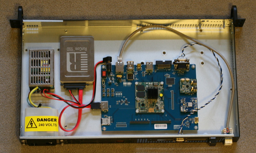
The board and SSD are mounted on nylon spacers. I would love to know how to countersink the screws into the bottom of the case properly: there is probably some sort of punch that you can use.
The power supply is a Traco Power TXL 025-05S. It has a single 5V output and is rated 25W; I got it from Farnell for about £25. Cheaper power supplies are available but I thought it wise to get something reputable. A slight concern is that the datasheet requires 60 mm clearance above the top for cooling; it's clearly not going to get that, but I'm running it well below its rated power output (see below).
The SSD was supplied with the Arndale board; there were suggestions that the board might not work with all SSDs, so this was a safe choice.
The layout was determined largely by the connectors on the Arndale board. It's unfortunate that they've not chosen to use a PC layout (e.g. Mini-ITX) as that would have suited existing enclosures. I considered mounting the board against the back of the case, but the position of the power connector makes that difficult; instead I've mounted it away from the sides of the case and brought out the couple of interfaces that I need with cables. Some care is needed to make sure you can still reach other connectors (e.g. HDMI) with the lid off.
It's not easy to find suitable connectors to bring out the ethernet to the back panel. I've chosen a "keystone" connector with punch-down terminals, which seems to work though I'm not convinced of its reliability. It would be worse if it were gigabit, but it's not.
When the board arrived, having spent almost 2 weeks in transit, the CPU daughter-board had fallen off the motherboard and was rattling around in the bag. I've therefore chosen to secure it with some nylon nuts and bolts.
Annoyingly, and like several other boards that I've used, this one powers up "off". You have to press a button to make it start. That's obviously not ideal once it is in a case. Fortunately, on this board you can simply solder a wire across this switch and the board will start up when the main power comes on.
Oddly, the serial port was wired as DCE. I've therefore swapped pins 2 and 3 to bring it out to my back pannel connector as DTE (there is no hardware flow control).
The board doesn't come with a heatsink. When I first powered it up, I measured 15 C above ambient in the middle of the CPU package while idle. I decided to fit a heatsink; this one is Farnell's part number 208-4434, and it's self-adhesive. Interestingly I now see a similar temparature with the thermocouple stuck between the fins of the heatsink. It can get up to about 21 C above ambient when the CPU is running flat out. Is it possible that the CPU is thermally regulated so that adding a heatsink allows it to run for longer at a higher clock speed?
Power consumption at the wall is about 5W idle and only slightly more when active.
I would like to bring out some LEDs to the front panel - at least, power and network activity would be useful. One option would be some sort of fibre optic light guide, if I can find something suitable.
The board comes with a couple of other daughter-boards, one for audio and one for WiFi; I don't need either and have removed them since taking the photo.
My intention is, of course, to run Debian armhf.
The board comes with Android on its eMMC. This is useful for confirming that the hardware is functional; it will output something on HDMI and the serial port.
I believe it is possible to debootstrap from Android, but I chose to install an Ubuntu image that Linaro have produced first. This is available at https://wiki.linaro.org/Boards/Arndale/Setup/EnterpriseUbuntuServer. You can install their image onto a uSD card, change some DIP switches on the board to boot from uSD rather than eMMC, and it will boot.
From Ubuntu it's possible to debootstrap onto the SSD. You do need to have functioning networking first though, and the board comes without a MAC address. (There is an i2c EEPROM connected to the ethernet chip that could have been programmed with a MAC address, but they don't seem to have done so.) Make the first byte 02 to indicate that the address is a locally-allocated unicast address, and the remaining 5 random; set it with "ifconfig hw ether address 02:nn:nn:nn:nn:nn". (It may also be possible to set this from U-Boot.)
The debootstrap process is something like this:
Debian should now boot, but I found that it would normally grind to a halt before getting as far as a login prompt. If this happens to you, you can pass init=/bin/sh to the kernel command line and get a root shell. Try "touch /etc/init.d/.legacy-bootordering" - this disables concurrent boot jobs, which made boot work reliably for me. I don't know what the underlying problem is here.
You can now "apt-get install" until the system is to your liking.
At this point, the system is still getting U-Boot and the kernel from the Linaro image on the uSD card. I would like it to boot from the eMMC and/or the SSD. U-Boot doesn't seem to know about the SATA system, so it looks like the kernel will have to come from eMMC. It appears that the Linaro U-Boot and the U-Boot supplied on the eMMC are very different versions, and my attempt to use the eMMC U-Boot to boot the Ubuntu kernel fails with "ERROR: booting os 'Invalid OS' (0) is not supported". So presumably I will need to put a different U-Boot onto the eMMC, or create a kernel image in whatever format this U-Boot will understand.
Linaro have instructions for copying their U-Boot and kernel from uSD to eMMC (attachment emmc_booting_doc.txt to the Linaro wiki page linked above). This involves "mmc read" and "mmc write" U-Boot commands to copy from one to the other; unfortunately, when I try it, U-Boot takes a suspiciously long time to complete the "mmc dev 1" command that makes the eMMC the current device, and then gives errors when I try to write or erase. I've also tried copying from Linux using dd; that appears to successfully copy the data, but when I boot from eMMC it is somehow still using the old version of U-Boot that I thought I had overwritten. That is as far as I have got.
Note that there seem to be two or three chained bootloaders; the Linaro and Arndale docs both refer to something called "BL1" that is supplied by Samsung and is prepended to U-Boot. I don't know what this is doing and what license or other issues there are with it.
My requirements from the kernel are quite modest, i.e. I don't need drivers for graphics etc. Things that seem to be missing from the Ubuntu kernel are NFS and the driver for the RTC.
I have downloaded a kernel from git://git.linaro.org/kernel/linux-linaro-tracking.git ; unlike the current vanilla kernel, this one has a selection of arndale config files. I don't know in what other ways it differs (no doubt a git expert would be able to work that out).
I have built this kernel with essentially the default config, and have installed it and its device tree (exynos5250-arndale.dtb) on an ext2 /boot. U-Boot can read these from the ext2 filesystem:
bootcmd=ext2load mmc 0 40007000 uImage; ext2load mmc 0 42000000 exynos5250-arndale.dtb; bootm 40007000
- 42000000
This seems to work, though I still don't have a working RTC. It doesn't seem to be mentioned in the device tree, though I'm sure I have come across it somewhere in the kernel source. This needs more investigation.